How To Make Rear Louvers for an SX/4
Submitted by amceaglenest.com member captspillane.
Here are the measurements to make your own rear louvers identical to the original set for your Eagle SX4 or Spirit. I am making several changes to these dimensions for my own sets and I will describe those changes in a separate post. I will offer these for sale as a kit in the near future.
First you need a set of points defined by letters. All the blades use the same set of dimensions for the ends except the top blade. I call the top blade number 1. There are seven total. To make the #1 blade you actually start off with the exact same pattern as well, then you trim more off. I’ll describe the #1 blade in a second post.
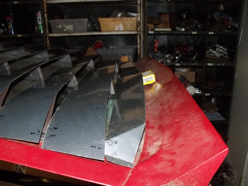
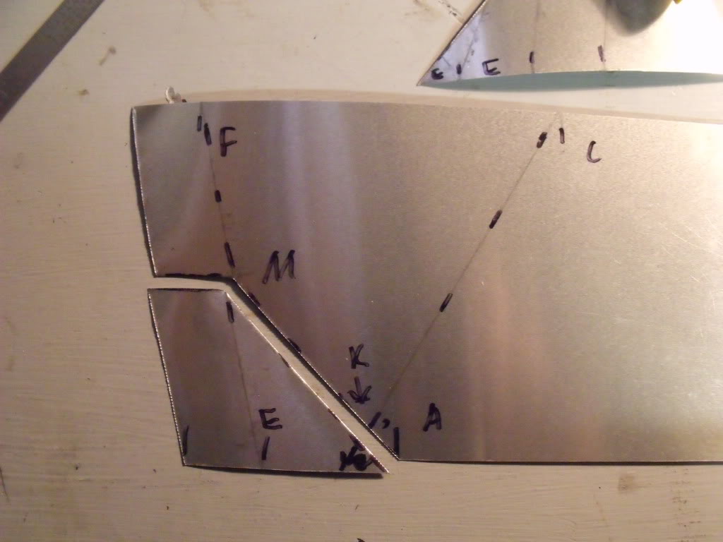
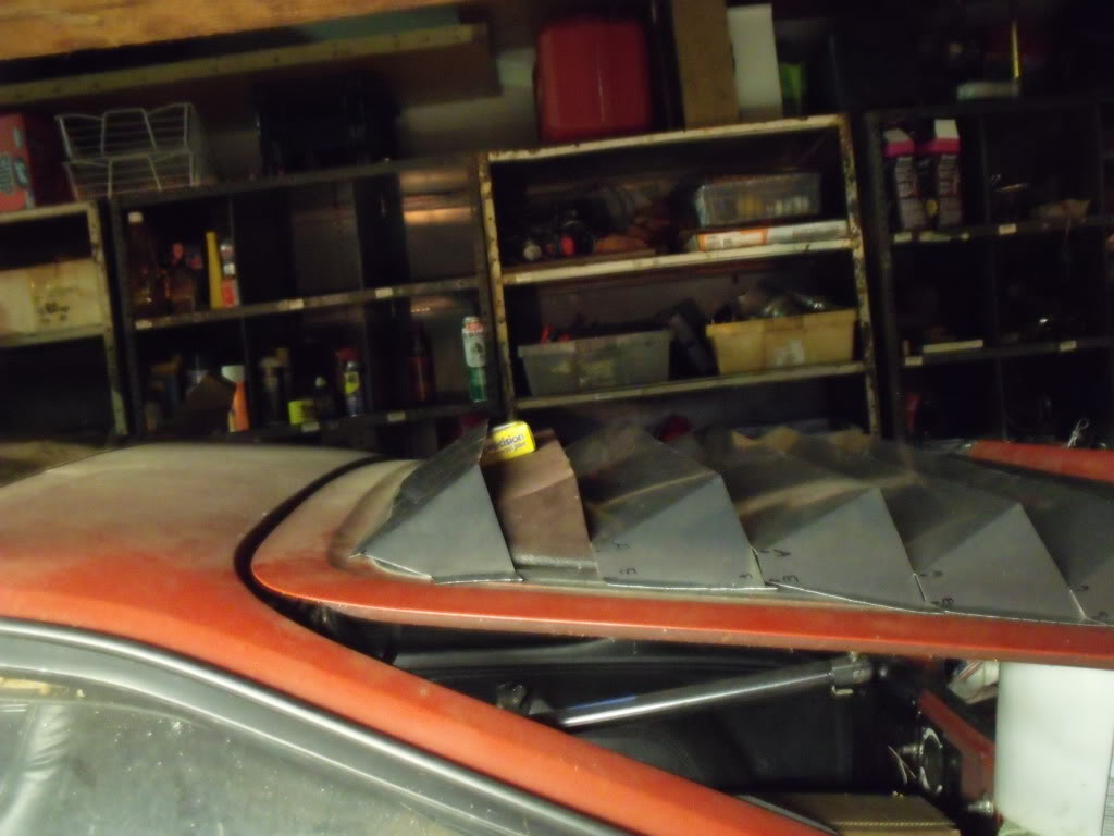
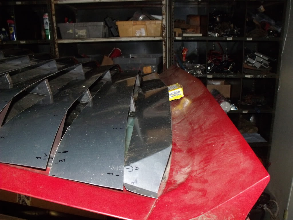
If you look closely at that picture you will see letters on my blades. There is a letter “A” inboard and a letter “C” outboard at either end of the primary crease. There is a letter “E” and a letter “F” exactly an inch from the end where I made another crease for the landing area. The secondary crease to make the inch wide landing area is just there for ease of mockup. “E” and “F” mark the extreme end of the original louvers.
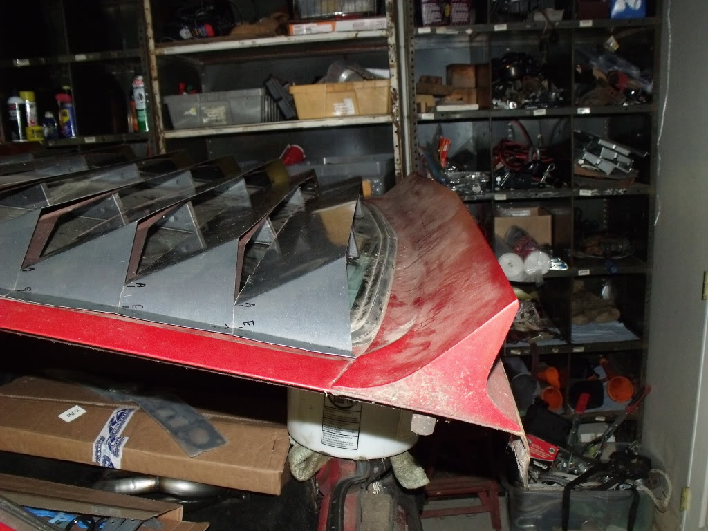
On the passenger side of the car I put an equivalent set of points with new letters. While “A” and “C” are the ends of the primary crease on the driver side, “B” and “D” are the ends of the crease on the passenger side. The extreme end called “E” to “F” on the driver side is called “G” to “H” on the passenger side. Here is the same picture after I put the creases in.
I also measured across the bottom of the louvers as a test to know if you angled the creases correctly.
Here are the precise measurements in inches, accurate to within 1/16 inches, for blades 2 through 7.
...A-B.......C-D.......E-G.......F-H.....A-E....C-F
2).39 1/8....33 3/4....41 1/4....42 1/4....1....4 3/4
3).40 1/8....34 3/4....42 1/4....43 1/4....1....4 3/4
4).41 1/8....35 3/4....43 1/4....44 1/4....1....4 3/4
5).42 1/8....36 3/4....44 1/4....45 1/4....1....4 3/4
6).43 1/8....37 3/4 45 1/4....46 1/4....1....4 3/4
7).44 1/8....38 3/4 46 1/4....47 1/4....1....4 3/4
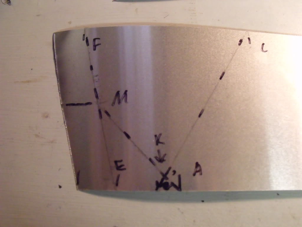
The first blade is different than the others. Here is a picture of the original set and my blade before and after I creased it.
If the first blade followed the obvious pattern made by the other seven, it would have an A,C, E, and F like the others do. In my pattern I created another letter, “Z”, to represent the extreme end of the primary crease that gets cut off later. “Z” on the first blade is where “A” should be if the first blade was shaped the same as the other blades.
The letters “C” and “F” are the same as the other blades. The letter “E” is still the end of the secondary crease, however you must cut at a point “M” along that line “E to F.” There is also a point “K” along the primary crease made from points “C to Z.” The letter “A” is along the forward edge of the blade. These letters should make sense when you look at the last two pictures.
Here are the dimensions:
- ) A-B C-D F-H Z-E C-F A-K M-F K-M
1) 37 32 3/4 41 1/4 1 4 3/4 1/2 2 3/8 2 3/8
The spacing between “A” and “Z” happens to be around 9/16.” That doesn’t actually help you mark them. I mark letters “C” and “D” first. I then mark the centerline at the half way point between “C” and “D.” That is 17-9/16” from “C” or “D.” I then used a square to continue the centerline across the blade to the forward edge. The point “A” is 18-1/2 inches from the centerline, while the point “Z” is 19-1/16” from the centerline.
I actually measured in that sequence for each blade I marked, including blades 2 through 7. I measured an inch from the extreme edge, marked “F”, then measured to mark “C,” then measured to mark “D,” then measured to mark the “G” and then the end at one inch past that. I then went back and marked the centerline between “C” and “D,” continued that centerline to the opposite edge with a square, and then marked “A” and “Z” from the centerline.
The width of the original blades themselves is 4-1/2.” I didn’t mention this earlier on purpose. One complaint I have of the original louvers is that they are too short. In my set I am making each one 3/8” wider. That 3/8” was added parallel to the rear edge only, so I actually used the same numbers from the last posting and then drew the new wider edge and just continued the crease lines with a straight edge instead of making a whole new set of measurements.
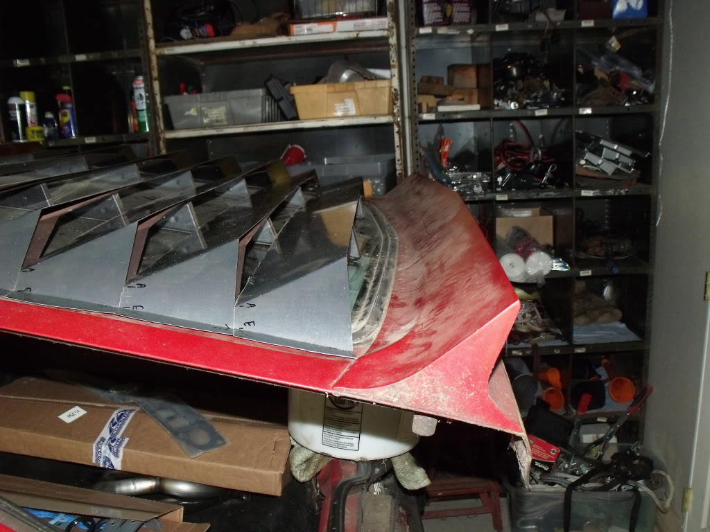
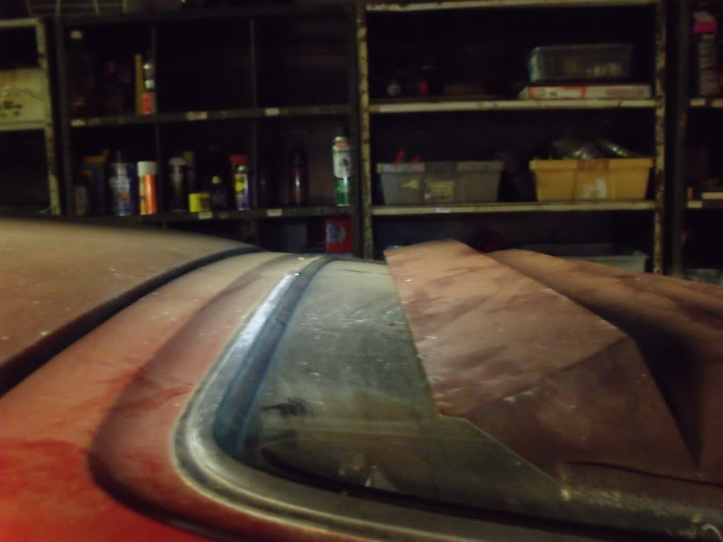
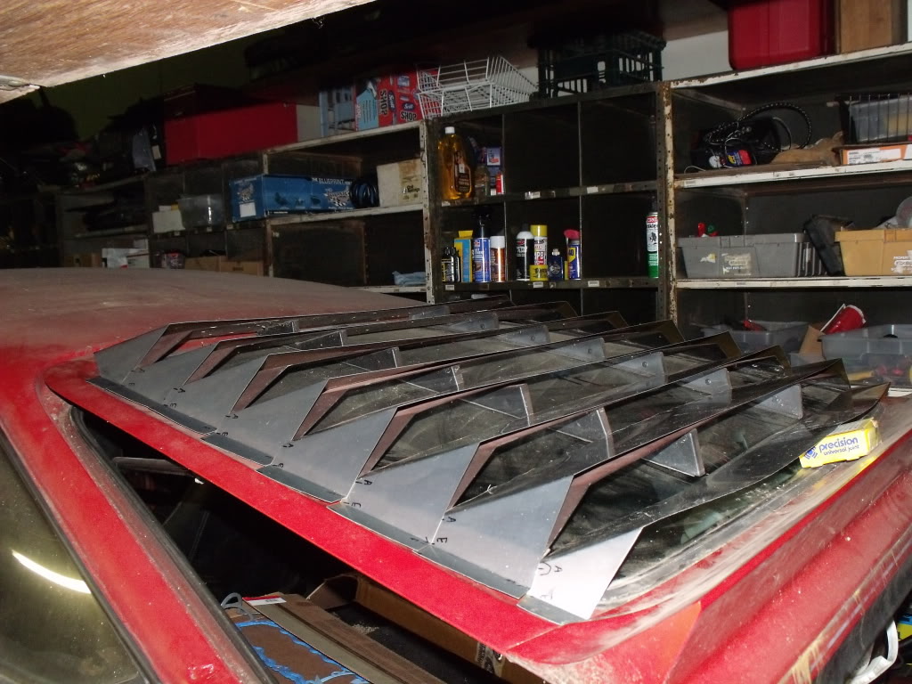
Adding 3/8” to all seven blades makes the entire set 2-5/8” longer. The first picture shows the louvers all the way to the bottom of the window. An original set would have a big space there that is exaggerated by the shape of the window. The second picture shows the space between the first blade and the top of the window while the louvers are slid down to where I want them to end. The third picture shows my first blade pushed up 2-5/8” to mimic where it will start on my elongated set.
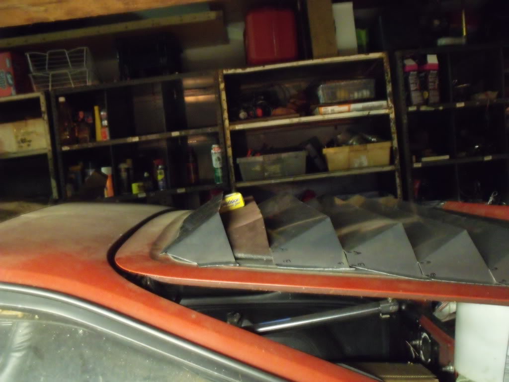
I experimented with an 8th blade added to fill the gap at the bottom. I made the back edge parallel to the spoiler. It doesn’t look bad but I think the first picture looks better. I’ve decided against adding an eighth blade to my louver sets. The last two pictures show that prototype I made.
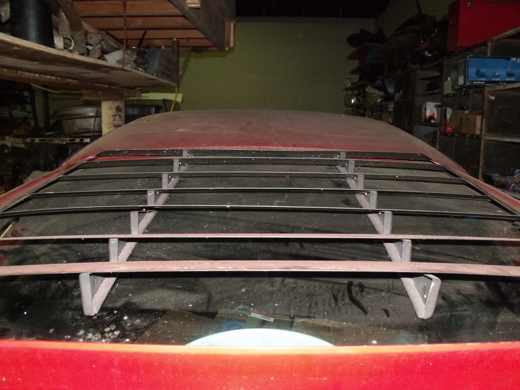
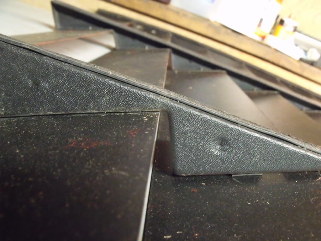
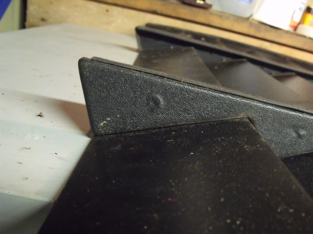
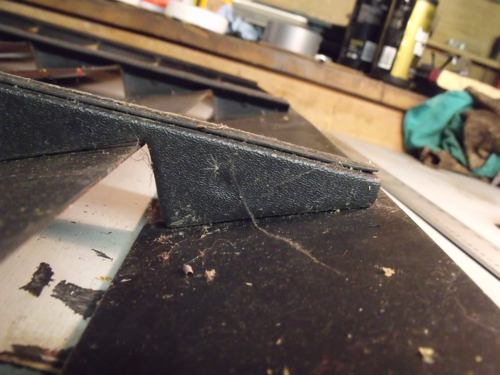
The supports on the underside have identical dimensions below blades 2 through 6. The dimensions below the first and last blade are a little bit different. For my dimensions I broke the shape into the rectangle parallel to the window and then seven right triangles supporting the blades sticking up from that rectangle. The Rectangle is 32” long and 3/8” thick with a 1/8” thick pad under, or a total of 1/2" thick. The right triangle has a short side nearly vertical between each blade that I called side “A” and a longer side of the triangle nearly horizontal up against each blade that I called side “B” and a hypotenuse parallel to the window that I called side “C”.
Side A: 1-3/4” long except for the last triangle, where it continues all the way to the window and has a total length of 2-1/4”
Side B: 4-1/8” long except for the top blade that is 3-7/8” long (its shorter so that it doesn’t hit the top window trim) and the bottom blade that is 4-5/8” long.
Side C: 4-3/8” long for all of them.
Each blade sits with two rivets on top of side “B.” The last blade #7 has side “A” flush with the end of the blade. The blade is 4-1/2” long and the side “B” is 4-5/8” long. That means there is a 1/8” space between the inboard or upper edge of the blade and the side “A” coming down from the blade above it. Likewise all of the other blades have exactly 1/8” space between their inner edge and the nearest side “A.” Since the side “B” is only 4-1/8” long for blades 2 through 6, and 1/8” of that isn’t covered by a blade, and the blades are 4-1/2 inches wide, that means that exactly a half inch of blade sticks out past the 90 degree corner of sides “A” and “B.” Since the blade below it also has an 1/8” space, the blades themselves actually overlap each other exactly 3/8.”
At the triangle under blade #1 the corner of sides “A” and “B” is still a 1/2" from the outer edge of the blade exactly like blades 2 through 6. At blade #1 Side “B” is only 3-7/8” because it is trimmed short straight down to the window while the blade overlaps it. That corner is usually pushed all the way up against the window trim when the louvers are installed.
I’ll modify my patterns to eliminate that pesky 1/8” space between side “A” and the blade below it. I’ll have everything flush.
The original hinges I do not have a picture of. The key to mounting them is getting them square to each other along the first blade. If they are not square to each other they will hinge bind against each other and not work. The original hinges mounted on a metal pedestal that bent inward to mount against the curved surface of the hatch, under the window trim, while keeping the hinges square.
The top two hinges held the top of the louvers down. The bottom of the louvers were held down by two fasteners along the edge of the sixth blade.
The original hinges are usually plastic with a weak spot in the center that hinges. They are often broken. A metal hinge from a hardware store replaces the old plastic one easily.
I personally had my louvers on my car for about a month. I had to make my own hinges and I could not get them strong enough to keep from flapping, making noise, and eventually coming loose. I had a strap to help them and was always deathly afraid of the louvers flying off and getting ruined. When most original louvers cost about $500 dollars now, that is a very real concern. My louvers will not mount in the same way as the original ones did.
I will have a piano hinge along either side of the louvers to fasten it to the liftgate. One side of the piano hinge will be bolted to the liftgate with a piece of curved metal that follows the natural body line and ends flush with the spoiler. It should look like it belongs there. The other side of the piano hinge will be attached to one of two “u” shaped support on each side that hinges open like a book. Two cross pieces at the top and the bottom will fasten the two halves of the book together. The louvers will then set on top of that support as an assembly. There will be no visible rivets or bolts on the outside of the louvers like the original ones had. Gussets will be added at the corners of the creases for a bolt to be inserted by hand out of sight parallel to the ground, threaded underneath the blade and hidden from view.
The original set of louvers were just wide enough for their finished edge to be flush with the inside edge of the window trim. In my revised set I made them wider by 1-3/16” on each side, or a total of 2-3/8” wider. They are just wide enough now to be flush with the outside edge of the window trim.
I will also make a “seamed” set that is less complex than the ones I’m mounting on my car. Instead of a seamless assembly mounted on two separate support assemblies, the whole louvers will have a seam in the middle and will hinge open like a book. Two cross pieces will bridge the two halves and secure them together with bolts underneath the blades, so there will still be no visible bolts or rivets on the outside of the louvers. These will be easier to box and ship ready to install for those on the nest who are less mechanically-savvy or well equipped to install the complex “seamless” sets.
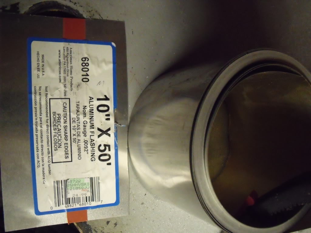
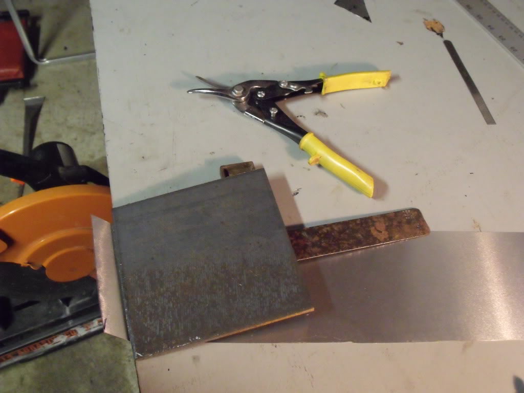
For my mock ups I am using a roll of aluminum flashing. The roll started off 10 inches wide. I cut the entire thing down to 4-1/2 inches wide with a miter saw and steel cutting blade. The number 7 blade is the longest. It requires 51-1/2 inches of material. Each blade is exactly one inch shorter than the one below it.
For those of you making your own set, I suggest using the same aluminum flashing to make a set of patterns. Once you have the patterns made you can even make a set of louvers out of the flashing in order to get the angle of the bend down perfect. There are plenty of shops who will have the brake and the tools to easily take those patterns and make a final product out of aluminum on your behalf.
The aluminum flashing is very easy to bend. I used a piece of 1/4 inch steel to pinch the flashing along my crease lines and then used my fingers as a brake to put in a nice crisp angle. I marked all of my measurements precisely with a pencil and then put a mark near it with a sharpie.
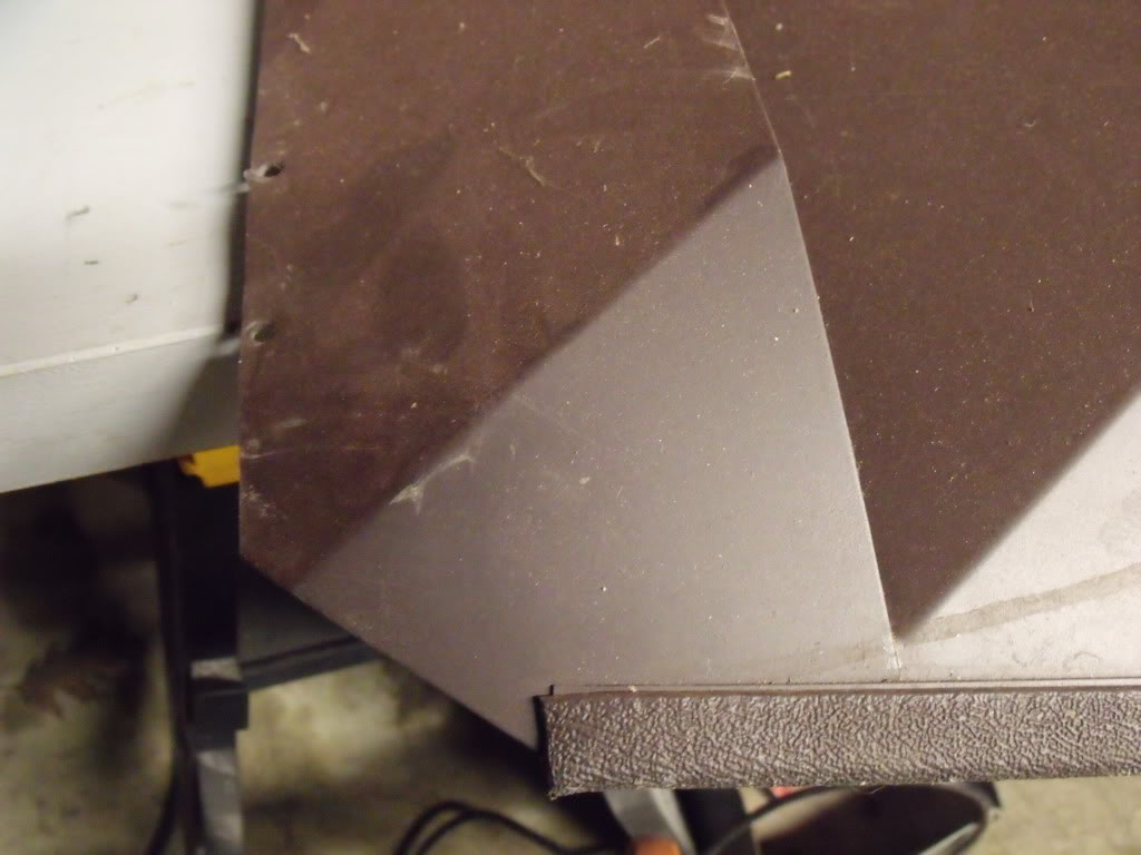
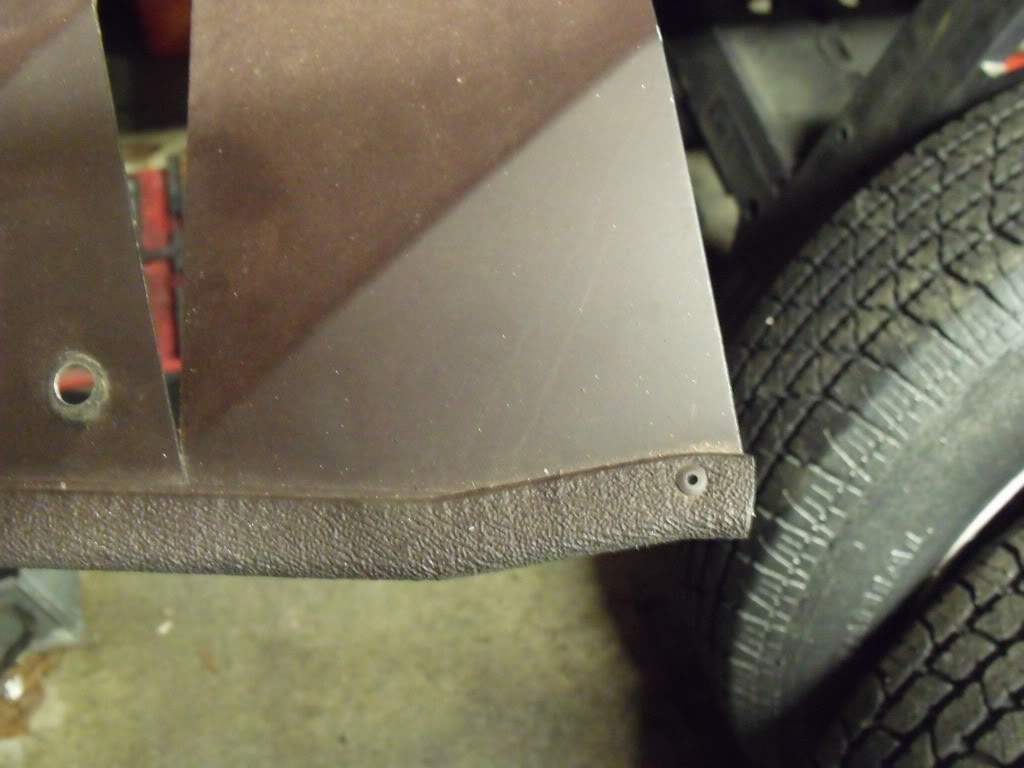
I also attached a picture here of the bottom of the seventh blade. The original set had a little bit shaved off the end. For my measurements I put a straight edge across and measured what it would be if it was straight and tight against the window. There is no need for that detail work unless you’re intent on keeping your louvers precisely original.
